


| Welcome to the FM-DW modules page ! |

FM-DW 2.2 main specs:
- Uses radio's dial for tuning. FM limits can be set for tuning in any direction.
- Preserves the radio's mono or stereo amplifier (tube or transistor).
- Easy configuration using a push-button and a dual color LED.
- No additional controls required, no external mods !
- Standard 87.5 - 108 MHz FM band with 50µs / 75µs de-emphasis choice.
- Supports both Japanese FM bands (76 - 90 MHz / 76 - 108 MHz).
- Supports AFC (Automatic Frequency Correction).
- Can be AC powered by tube heaters circuit (parallel heaters only).
- Can be DC powered (4V to 16V - minimum 6V if using the +5V output).
- On-board +5V 50mA regulated DC output for accessory (Bluetooth or other).
- Compact and easy to install: 3 cm x 3.6 cm, three 2.6mm grounded holes.
- Only requires a simple wire antenna (3ft is sufficient in most cases).
- Optional AM Saver module (sold separately).
- Pads referenced on silkscreen for easy installation.
- Pad for connecting a separate push-button.
- URL of this page on bottom side of module.
FM-DW 3.0 main specs (in addition to those above):
- ESD protected antenna circuit.
- Supports variable inductors (vintage car radios) and potentiometers for tuning.
- Drives most magic eye tubes for signal strength.
AM-Saver main specs:
- Sits over the FM-DW 2.0, 2.1, 2.2 and 3.0 modules.
- Power: 4 to 6 volts DC or AC (6.3Vac with diode in series).
- Preserves the AM bands using a single switch to commute between AM and FM.
- Can disable the AM frequency changer in FM mode if required.
Important notes:
The FM-DW 2.x modules only work with an AM tuning capacitor.
FM-DW 3.0 adds support for local oscillator tuning (more stable), which
works with a tuning capacitor and with variable inductors (vintage car radios).
It can also tune using a potentiometer.
If using the AM Saver, ensure that the tuning capacitor be not originally
connected to high voltage otherwise the FM-DW module will be damaged by
any residual charge when switching.
DAB/DAB+ radios can only be heard using a DAB/DAB+ to FM transmitter,
which avoids altering the radio to insert additional controls and a LCD
screen.
The AM bands can be preserved using the optional AM Saver "piggy-back"
module or a custom switching circuit.
Installing FM-DW 3.0 only for FM reception
To install while keeping the AM bands active, scroll down or click here.
The FM-DW module uses electrostatically sensitive components:
installation and setup must be carried out by a person with sufficient electronics experience
(especially in the restoration of vintage tube and transistor radios) to avoid damage,
otherwise you install and use the FM-DW modules at your own risk.
FM-DW 3.0 modules are individually tested before dispatch to ensure that they arrive in
perfect condition. Any module returned will be closely inspected to determine if it has been
damaged by improper installation or tampering, in which case it will not be replaced or refunded.
Make sure that your radio has been properly restored and that its amplifier is working properly.
Keep the radio unplugged from the mains during the entire installation process.
Your radio's mains switch must be clean and not produce excessive arcing.
If necessary, a suppressor capacitor can be connected in parallel.
Disabling the IF sections: As we will no longer be using the AM bands, the IF sections can
be disabled depending on the type of tuner by disconnecting the plate and screen grid circuits.
- For variable inductor tuners, the local oscillator section must be working.
The second IF stage can be disabled.
- For other tuning methods (tuning capacitor or potentiometer) the IF sections can be completely disabled.
IF tubes can only be removed if their heaters are connected in parallel. When removing the
second IF tube, ensure that it does not contain a triode used in the LF amplifier circuit.
If the high voltage increases too much after the IF section has been disabled,
the DC filter should be adjusted with a higher resistor (or a resistor added in
series with the loudspeaker field coil).
Before all, the FM-FW module should be placed away from heat sources
such as rectifier and output tubes. It is recommended to place it under the chassis.
At temperatures above 50°C, the FM-DW 2.0 and 2.1 modules will suffer from drift until the temperature cools down.
FM-DW 2.2 and 3.0 modules use a different FM chip, making them significantly more tolerant.
Grounding the FM-DW module: except for vintage car radios with positive ground, the FM-DW
module should be grounded to the chassis (this is very important for AC/DC sets).
Its three grounding holes allow a solid attachment.
Setting the operating mode: The FM-DW 3.0 supports three modes for detecting
the dial position and tuning to the corresponding FM channel. The default one is
Capacitive, which requires a connection to the AM tuning capacitor and no restoration
of the useless IF sections.
The Local Oscillator (L.O.) mode allows the FM-DW 3.0 to work with most AM radios
(including vintage car radios), whether they use a tuning capacitor or variable inductance
for tuning.
The Resistive mode uses a linear potentiometer mechanicaly coupled to the dial mechanism.
To enable the L.O. mode, bridge the two halves of the Osc pad in the Mode section.
To enable the resistive mode, bridge the two halves of the Pot pad in the Mode section.
Note: Changing the operating mode after the setup is complete will reset the module.
For the capacitive mode: The condition of the tuning capacitor is critical.
Permanent contact between the shaft and the collectors is essential. Ensure that there is no
excessive dust between the plates and that there are no short-circuits when the tuning capacitor
is rotated from end to end. Either of these faults can distort the capacitance measurements,
resulting in incorrect setup data and unstable (if not impossible) tuning.
The body of the tuning capacitor must be grounded, and all ground points should be connected, which will
reduce weak collector contacts.
For DC radios with a positive chassis (especially early transistor models), ensure that the tuning
capacitor body is insulated from the chassis.
The tuning capacitor must be connected to the FM-DW module pad marked with a variable
capacitor symbol. Nothing else should be left connected to the tuning capacitor, except capacitive
trimmers which can be set to their maximum.
Grouping the sections of the tuning capacitor is not essential, but may be necessary in some cases:
the minimum capacitance should be 40pF to 100pF (add a small fixed capacitor in parallel if necessary),
and the maximum capacitance should be 500pF to 1000pF.
For the L.O. mode: The local oscillator circuit is extremely sensitive and
should be connected with care. To prevent parasitic capacitance from altering the signal,
connect the L.O. signal from the AM tuner to the octagonal Osc pad (under the Antenna pad)
using the shortest possible wire, and avoid placing the wire close to other wires or near metal parts.
On tube radios, the L.O. signal is located at the grid of the oscillator tube:
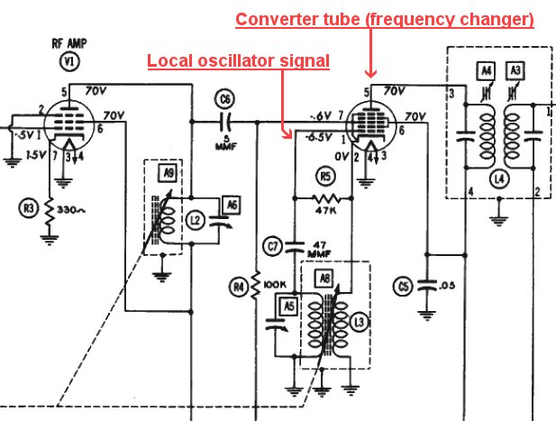
Oscillator signal at a single-element frequency converter tube. Click to enlarge. |
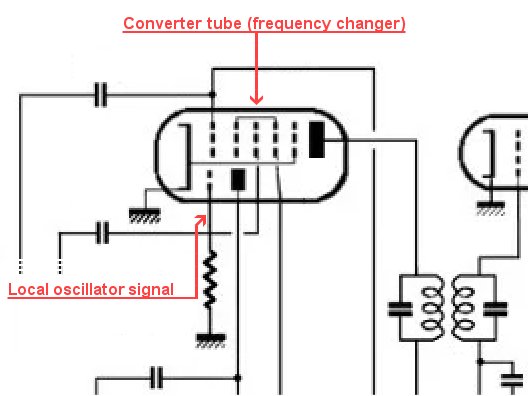
Oscillator signal at a two-element frequency converter tube. Click to enlarge. |
On transistor radios equipped with variable inductors, the L.O. signal is located at the oscillator coil connected to the oscillator transistor. This transistor is usually located between the first one (often called the RF Amplifier) and the third one (often called the Mixer, itself just before the first IF transformer).
On transistor radios equipped with a tuning capacitor, the L.O. signal is easily found at one of the tuning capacitor sections.
If in doubt, the L.O. signal can easily be found using an oscilloscope.
For the resistive mode: The tuning is done using a 10K to 50K linear potentiometer, which must not produce jitter. This mode lets you replace a damaged tuning capacitor with a potentiometer, which metal shaft is attached to the original dial cord pulley. The potentiometer connects to the three Tuning Pot pads located in the middle of the top side of the module. The cursor connects to the center pad. As the FM band can be set to start at either side of the dial, the other two pins of the potentiometer connect to the remaining pads in no particular order.
The FM-DW AC/DC in pad supplies the FM-DW module with AC (4V to 10V) or DC (see below).
A heater winding supplying 4V to 10V AC can be connected directly to the FM-DW module if it has one grounded side and no center tap (Fig. 1).
A voltage doubler is required if this heater winding outputs 2.5V to 4V AC (Fig. 2).
If the heater winding has a grounded center tap and outputs 2.5V to 4V AC, a voltage doubler is required (Fig. 3).
If it outputs 6.3V AC, use either half with a voltage doubler as shown in Fig. 2.
Radios with heaters connected in series must use a separate DC power supply that provides sufficient current :
- The radio section of the FM-DW module draws less than 50mA.
- When used, the on-board +5V regulated power supply can provide up to 50mA.
- When using the on-board +5V regulated output, the minimum DC voltage is 6V (otherwise 4V).
For car radios, the AC/DC in pad must be connected to the +6V or +12V supply. In the case of positive ground (i.e. the car chassis is connected to the positive side of the battery), ensure that none of the grounded holes of the FM-DW module be connected to the chassis. The FM-DW module is protected against reverse polarity.
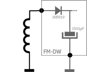 Fig. 1: powering the FM-DW module using a grounded heater winding of 4Vac to 10Vac. |
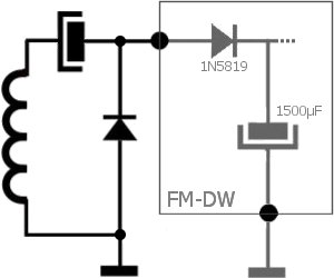 Fig. 2: powering the FM-DW module using a grounded heater winding (2.5V to 4V AC) with no center tap. |
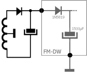 Fig. 3: powering the FM-DW module using a grounded center-tapped heater winding (2.5V to 4V AC). |
The FM-DW Antenna pad is connected differently depending on your configuration.
Remove anything previously connected to the radio's antenna connector and connect it to the FM-DW Antenna pad.
For AC/DC home sets, a 1 megohm resistor should be connected between the FM-DW antenna pad and the chassis. A simple 3ft antenna cable is sufficient in most cases.
For car radios, disconnect the AM filter originally connected at the antenna input. This filter is usually made of a capacitor trimmer and an inductor, and can considerably attenuate the FM signal.
The FM-DW L OUT pad can be used with mono receivers. Radios equipped with a stereo amplifer will use it as the left channel source. Connect the L OUT pad to the LF amplifier input after disconnecting the detector circuit. For AC/DC radios, a 0.01µF/630V capacitor should be inserted before the amplifier input if not already present by design. Its value is not critical. A shielded cable should be used except for short lengths. Remember that only one end of the shield must be grounded.
The FM-DW R OUT pad is only required for radios equipped with a stereo amplifier. As with the L OUT pad, the R OUT pad is connected to the right channel input of the LF amplifier (after checking that the detector circuit is no longer connected to it).
The FM-DW Magic Eye pad allows the Magic Eye tube to be used as an FM signal strength indicator. Disconnect the grid of the Magic Eye tube from the AM circuits, and connect the Magic Eye pad to it instead. Most types of Magic Eye tubes used in old AM radios are supported, with maximum grid voltage adjustable to -10 volts during the setup.
The FM-DW Setup pad allows the connection of an additional setup pushbutton, the other end of which must be grounded.
D o u b l e C h e c k y o u r w i r i n g before configuring the FM-DW module.
Installing FM-DW 3.0 with AM-Saver
To install without AM bands, scroll up to the previous section or click here.
The FM-DW module uses electrostatically sensitive components:
installation and setup must be carried out by a person with sufficient electronics experience
(especially in the restoration of vintage tube and transistor radios) to avoid damage,
otherwise you install and use the FM-DW modules at your own risk.
FM-DW 3.0 modules are individually tested before dispatch to ensure that they arrive in
perfect condition. Any module returned will be closely inspected to determine if it has been
damaged by improper installation or tampering, in which case it will not be replaced or refunded.
Make sure that your radio has been properly restored and that its amplifier is working properly.
Keep the radio unplugged from the mains during the entire installation process.
Your radio's mains switch must be clean and not produce excessive arcing.
If necessary, a suppressor capacitor can be connected in parallel.
Before all, the FM-FW module should be placed away from heat sources
such as rectifying and output tubes. It is recommended to place it under the chassis.
At temperatures over 50°C, the FM-DW 2.0 and 2.1 modules will suffer from drift until the temperature cools down.
FM-DW 2.2 and 3.0 modules use a different FM chip, making them significantly more tolerant.
Grounding the FM-DW module: except for vintage car radios with positive ground, the FM-DW
module should be grounded to the chassis (this is very important for AC/DC sets).
Its three grounding holes allow a solid attachment.
Setting the operating mode: The FM-DW 3.0 supports three modes for detecting
the dial position and tuning to the corresponding FM channel. The default one is
Capacitive, which requires a connection to the AM tuning capacitor. In this
mode, the Magic Eye tube cannot be used as an FM signal strength indicator unless it is
permanently disconnected from the AGC circuit of the AM section.
The Local Oscillator (L.O.) mode allows the FM-DW 3.0 to work with most AM radios
(including vintage car radios), whether they use a tuning capacitor or variable inductance
for tuning. In this mode, the Magic Eye tube can be used to indicate the FM signal strength
as the AM Saver module will switch its grid connectio between the AM and FM circuits.
The Resistive mode uses a linear potentiometer mechanicaly coupled to the dial mechanism.
To enable the L.O. mode, bridge the two halves of the Osc pad in the Mode section.
To enable the resistive mode, bridge the two halves of the Pot pad in the Mode section.
Note: Changing the operating mode after the setup is complete will reset the module.
For the capacitive mode: The condition of the tuning capacitor is critical.
Permanent contact between the shaft and the collectors is essential. Ensure that there is no
excessive dust between the plates and that there are no short-circuits when the tuning capacitor
is rotated from end to end. Either of these faults can distort the capacitance measurements,
resulting in incorrect setup data and unstable (if not impossible) tuning.
The body of the tuning capacitor must be grounded, and all ground points should be connected, which will
reduce weak collector contacts.
For DC radios with a positive chassis (especially early transistor models), ensure that the tuning
capacitor body is insulated from the chassis.
The tuning capacitor will be connected to the AM Saver module later.
For tube radios, ensure that the fixed plates of the tuning capacitor are not originally connected
to a high voltage source, otherwise the FM-DW module may be permanently damaged by residual charges
when switching between AM and FM.
For the L.O. mode: The local oscillator circuit is extremely sensitive and
should be connected with care. To prevent parasitic capacitance from altering the signal,
connect the L.O. signal from the AM tuner to the octagonal Osc pad (under the Antenna pad)
using the shortest possible wire, and avoid placing the wire close to other wires or near metal parts.
On tube radios, the L.O. signal is located at the grid of the oscillator tube:
|
Oscillator signal at a single-element frequency converter tube. Click to enlarge. |
Oscillator signal at a two-element frequency converter tube. Click to enlarge. |
On transistor radios equipped with variable inductors, the L.O. signal is located at the oscillator coil connected to the oscillator transistor. This transistor is usually located between the first one (often called the RF Amplifier) and the third one (often called the Mixer, itself just before the first IF transformer).
On transistor radios equipped with a tuning capacitor, the L.O. signal is easily found at one of the tuning capacitor sections.
If in doubt, the L.O. signal can easily be found using an oscilloscope.
For the resistive mode: The tuning is done using a 10K to 50K linear potentiometer, which must not produce jitter. This mode lets you replace a damaged tuning capacitor with a potentiometer, which metal shaft is attached to the original dial cord pulley. The potentiometer connects to the three Tuning Pot pads located in the middle of the top side of the module. The cursor connects to the center pad. As the FM band can be set to start at either side of the dial, the other two pins of the potentiometer connect to the remaining pads in no particular order.
As a reminder, AM bands can only be preserved if the potentiometer is mechanically coupled to the AM tuning system.
The FM-DW AC/DC in pad supplies the FM-DW module with AC (4V to 10V) or DC (see below).
The AC/DC in pad of the AM Saver module accepts 4 to 6 volts (AC or DC) and will be connected later.
A heater winding supplying 4V to 10V AC can be connected directly to the FM-DW module if it has one grounded side and no center tap (Fig. 1).
A voltage doubler is required if this heater winding outputs 2.5V to 4V AC (Fig. 2).
If the heater winding has a grounded center tap and outputs 2.5V to 4V AC, a voltage doubler is required (Fig. 3).
If it outputs 6.3V AC, use either half with a voltage doubler as shown in Fig. 2.
Radios with heaters connected in series must use a separate DC power supply that provides sufficient current :
- The radio section of the FM-DW module draws less than 50mA.
- When used, the on-board +5V regulated power supply can provide up to 50mA.
- When using the on-board +5V regulated output, the minimum DC voltage is 6V (otherwise 4V).
For car radios, the AC/DC in pad must be connected to the +6V or +12V supply. In the case of positive ground (i.e. the car chassis is connected to the positive side of the battery), ensure that none of the grounded holes of the FM-DW module be connected to the chassis. The FM-DW module is protected against reverse polarity.
Fig. 1: powering the FM-DW module using a grounded heater winding of 4Vac to 10Vac. |
Fig. 2: powering the FM-DW module using a grounded heater winding (2.5V to 4V AC) with no center tap. |
Fig. 3: powering the FM-DW module using a grounded center-tapped heater winding (2.5V to 4V AC). |
The FM-DW Antenna pad connects to the radio's antenna connector.
For AC/DC home sets, a 1 megohm resistor should be connected between the FM-DW antenna pad and the chassis. A simple 3ft antenna cable is sufficient in most cases.
The FM-DW L OUT and R OUT pads will be connected to the AM Saver by vertical straps later.
The FM-DW Setup pad allows the connection of an additional setup pushbutton, the other end of which must be grounded. The AM Saver has a hole to allow access to the FM-DW pushbutton.
Mount the AM Saver module on top of the FM-DW module using metal spacers (4mm outer diameter) as shown in Fig. 4, ensuring that they do not short circuit other pads as they connect the grounds of the two modules.
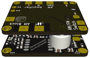
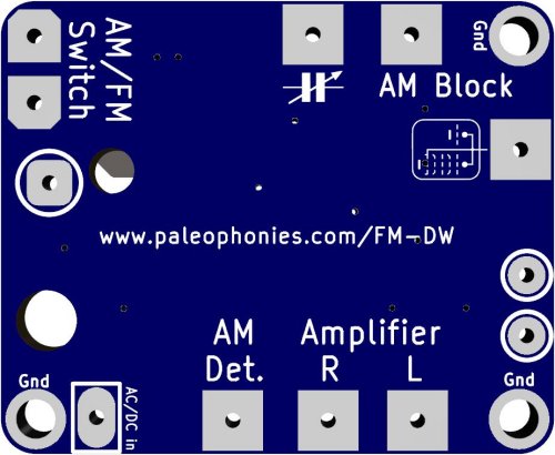 Fig. 4: AM Saver over the FM-DW module, and AM Saver connection pads. |
The AM Saver accepts 4 to 6 volts (AC or DC), in which case a vertical strap must be placed between the AC/DC IN pads of the two modules. If the FM-DW module is supplied with more than 6Vac, a rectifier diode must be used instead of the strap, with the anode connected to the FM-DW module. This diode must have a voltage drop of 0.6V to 1.2V and a forward current of at least 200mA. Additional series-connected diodes are required if the FM-DW module is powered from a higher voltage. Ensure that there is not more than 6V DC at the main electrolytic capacitor of the AM Saver module. Excessive voltage will cause the on-board regulator to overheat and shut-down by security.
Depending on your configuration, several vertical straps must be connected between the AM Saver pads circled in white (see Fig. 4) and the FM-DW pad underneath.
Strap each the two AM Saver pads on the right with its corresponding FM-DW Audio Out pad.
If you are using the Capacitive Mode:
- Place a vertical strap between the AM Saver pad located below the two AM / FM Switch pads and the FM-DW Tuning Capacitor pad.
- Disconnect what was originally connected to the Oscillator Section of the tuning capacitor (except capacitive trimmers) and connect connect it to the AM Block pad of the AM Saver with the shortest possible wire.
- Connect the the freeed Oscillator section of the tuning capacitor to the Tuning Capacitor pad of the AM Saver with the shortest possible wire to avoid adding too much capacitance.
Due to the increased capacitance, the AM local oscillator should be checked and possibly adjusted prior to the FM-DW setup.
In Local Oscillator Mode, the Magic Eye tube can be used with AM and FM bands:
- Connect the AM Saver pad located below the two AM / FM Switch pads to the FM-DW Magic Eye pad.
- Disconnect the grid of the Magic Eye tube at its socket and connect the wire the AM Block pad of the AM Saver.
- Connect the grid of the Magic Eye tube to the Tuning Capacitor pad of the AM Saver.
The Amplifier L-R pads of the AM Saver must be connected to the LF amplifier input(s). Shielded cable(s) should be used except for short lengths. Remember that only one end of the shield must be grounded.
The Amplifier R pad is only required for radios equiped with a stereophonic amplifier.
The Amplifier L pad is used with mono receivers.
For AC/DC radios, a 0.01µF/630V capacitor should be inserted before the amplifier input if not already present by design. Its value is not critical.
The AM Det. pad of the AM Saver must be connected to the AM detector (which must be disconnected from the LF Amplifier input).
The Vaccuum Tube pad is used only when the AM section perturbates the FM reception, in which case a small modification must be applied to the frenquency changer tube circuit as shown in Fig. 5.
The grid resistor (usually 25K to 47K Ohms) must be left grounded.
If originally grounded, disconnect the cathode from ground, and add a 82 ohms resistor between the cathode and the AM Saver pad designated by a vaccuum tube symbol.
If the cathode was originally grounded through a parrallel resistor and capacitor (or a resistor alone), disconnect them (or the resistor) from ground, and connect them (or the resistor) to the AM Saver pad designated by a vaccuum tube symbol.
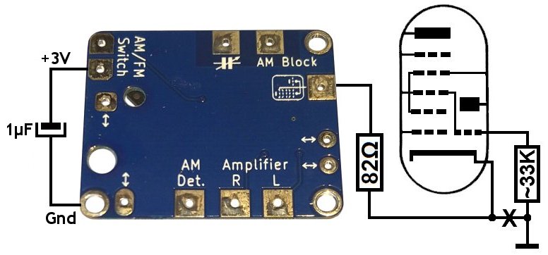
Fig. 5: AM Saver pads and optional circuit. |
The two AM/FM Switch pads connect to an external switch enabling the AM bands when closed. Two terminals of the band selector may be used provided that they be never connected to anything whatever the switch position, and that they remain connected only at the positions corresponding to the AM bands. A microswitch (SPDT with lever) may also be used to detect the mechanical position of the FM band. Otherwise, a separate switch must be used.
Connect the 1µF capacitor as shown on on Fig. 5.
D o u b l e C h e c k y o u r w i r i n g before turning the radio on to configure the FM-DW module.
Installing FM-DW 2.0 / 2.1 / 2.2 alone
To install while keeping the AM bands active, scroll down or click here.
The FM-DW module uses electrostatically sensitive components:
installation and setup must be carried out by a person with sufficient electronics experience
(especially in the restoration of vintage tube and transistor radios) to avoid damage,
otherwise you install and use the FM-DW module (and possibly the AM Saver module) at your own risk.
FM-DW 2.2 modules are individually tested before dispatch to ensure that they arrive in
perfect condition. Any module returned will be closely inspected to determine if it has been
damaged by improper installation or tampering, in which case it will not be replaced or refunded.
Make sure that your radio has been properly restored and that its amplifier is working properly.
Keep the radio unplugged from the mains during the entire installation process.
Your radio's mains switch must be clean and not produce excessive arcing.
If necessary, a suppressor capacitor can be connected in parallel.
As we will no longer be using the AM bands, the IF section is no longer required.
You can therefore disconnect the plate and screen grid circuits of the IF
tubes, and remove the IF tubes if their heaters are connected in parallel.
If the high voltage increases too much after the IF section has been disconnected,
the DC filter should be adjusted with a higher resistor (or a resistor added in
series with the loudspeaker field coil).
Before all, the FM-FW module should be placed away from heat sources
such as rectifying and output tubes. It is recommended to place it under the chassis.
At over 50°C, the FM-DW 2.0 and 2.1 modules will suffer from drifts until temperature cools down.
FM-DW 2.2 modules use a different FM chip, making them significantly more tolerant.
Ground the FM-DW module to the chassis (very important with AC/DC sets).
Its three grounded holes allow a solid attachment.
The condition of the tuning capacitor is critical: permanent contact between the shaft and the
collectors is essential. Ensure that there is no excessive dust between the plates and that there are no
short-circuits when the tuning capacitor is rotated from end to end. Either of these faults can distort the
capacitance measurements, resulting in incorrect setup data and unstable (if not impossible) tuning.
The body of the tuning capacitor must be grounded, and all ground points should be connected, which will
reduce weak collector contacts.
For DC radios with a positive chassis (especially early transistor models), ensure that the tuning
capacitor's body is insulated from the chassis.
The tuning capacitor must be connected to the FM-DW module pad marked with a variable
capacitor symbol. Nothing else should be left connected to the tuning capacitor, except capacitive
trimmers which can be set to their maximum.
Grouping the sections of the tuning capacitor is not essential, but may be necessary in some cases:
the minimum capacitance should be 40pF to 100pF (add a small fixed capacitor in parallel if necessary),
and the maximum capacitance should be 500pF to 1000pF.
The FM-DW AC/DC in pad supplies the FM-DW module with AC (4V to 10V) or DC (see below).
A heater winding supplying 4V to 10V AC can be connected directly to the FM-DW module if it has one grounded side and no center tap (Fig. 1).
A voltage doubler is required if this heater winding outputs 2.5V to 4V AC (Fig. 2).
If the heater winding has a grounded center tap and outputs 2.5V to 4V AC, a voltage doubler is required (Fig. 3).
If it outputs 6.3V AC, use either half with a voltage doubler as shown in Fig. 2.
Radios with heaters connected in series must use a separate DC power supply that provides sufficient current :
- The radio section of the FM-DW module draws less than 50mA.
- When used, the on-board +5V regulated power supply can provide up to 50mA.
- When using the on-board +5V regulated output, the minimum DC voltage is 6V (otherwise 4V).
Fig. 1: powering the FM-DW module using a grounded heater winding of 4Vac to 10Vac. |
Fig. 2: powering the FM-DW module using a grounded heater winding (2.5V to 4V AC) with no center tap. |
Fig. 3: powering the FM-DW module using a grounded center-tapped heater winding (2.5V to 4V AC). |
The FM-DW Antenna pad is connected differently depending on your configuration.
For AC/DC sets, a 1-megohm resistor should be added between the FM-DW antenna pad and the chassis.
Remove anything previously connected to the radio's antenna connector and connect it to the FM-DW Antenna pad.
A 120 ohm antenna is recommended (a 3ft cable is sufficient in most cases).
The FM-DW L OUT pad can be used with mono receivers. Radios equipped with a stereo amplifer will use it as the left channel source. Connect the L OUT pad to the LF amplifier input after disconnecting the detector circuit. For AC/DC radios, a 0.01µF/630V capacitor should be inserted before the amplifier input if not already present by design. Its value is not critical. A shielded cable should be used except for short lengths. Remember that only one end of the shield must be grounded.
The FM-DW R OUT pad is only required for radios equipped with a stereo amplifier. As with the L OUT pad, the R OUT pad is connected to the right channel input of the LF amplifier (after checking that the detector circuit is no longer connected to it).
The FM-DW Setup pad allows the connection of an additional setup pushbutton, the other end of which must be grounded.
D o u b l e C h e c k y o u r w i r i n g before configuring the FM-DW module.
Installing FM-DW 2.0 / 2.1 / 2.2 with AM-Saver
To install without AM bands, scroll up to the previous section or click here.
The FM-DW module uses electrostatically sensitive components:
installation and setup must be carried out by a person with sufficient electronics experience
(especially in the restoration of vintage tube and transistor radios) to avoid damage,
otherwise you install and use the FM-DW module (and possibly the AM Saver module) at your own risk.
FM-DW 2.2 modules are individually tested before dispatch to ensure that they arrive in
perfect condition. Any module returned will be closely inspected to determine if it has been
damaged by improper installation or tampering, in which case it will not be replaced or refunded.
Make sure that your radio has been properly restored and that its amplifier is working properly.
Keep the radio unplugged from the mains during the entire installation process.
Your radio's mains switch must be clean and not produce excessive arcing.
If necessary, a suppressor capacitor can be connected in parallel.
Before all, the FM-FW module should be placed away from heat sources such as rectifying
and output tubes. It is recommended to place it under the chassis. At over 50°C, the FM-DW 2.0
and 2.1 modules will suffer from drifts until temperature cools down.
FM-DW 2.2 modules use a different FM chip, making them significantly more tolerant.
Ground the FM-DW module to the chassis (very important with AC/DC sets).
Its three grounded holes allow a solid attachment.
The condition of the tuning capacitor is critical: permanent contact between the shaft and the
collectors is essential. Ensure that there is no excessive dust between the plates and that there are no
short-circuits when the tuning capacitor is rotated from end to end. Either of these faults can distort the
capacitance measurements, resulting in incorrect setup data and unstable (if not impossible) tuning.
The body of the tuning capacitor must be grounded, and all ground points should be connected, which will
reduce weak collector contacts.
For DC radios with a positive chassis (especially early transistor models), ensure that the tuning
capacitor's body is insulated from the chassis.
For tube radios, ensure that the fixed plates of the tuning capacitor are not originally connected
to a high voltage source, otherwise the FM-DW module may be permanently damaged by residual charges
when switching between AM and FM.
The FM-DW AC/DC in pad supplies the FM-DW module with AC (4V to 10V) or DC (see below).
The AC/DC in pad of the AM Saver module accepts 4 to 6 volts (AC or DC) and will be connected later.
A heater winding supplying 4V to 10V AC can be connected directly to the FM-DW module if it has one grounded side and no center tap (Fig. 1).
A voltage doubler is required if this heater winding outputs 2.5V to 4V AC (Fig. 2).
If the heater winding has a grounded center tap and outputs 2.5V to 4V AC, a voltage doubler is required (Fig. 3).
If it outputs 6.3V AC, use either half with a voltage doubler as shown in Fig. 2.
Radios with heaters connected in series must use a separate DC power supply that provides sufficient current :
- The radio section of the FM-DW module draws less than 50mA.
- When used, the on-board +5V regulated power supply can provide up to 50mA.
- When using the on-board +5V regulated output, the minimum DC voltage is 6V (otherwise 4V).
Fig. 1: powering the FM-DW module using a grounded heater winding of 4Vac to 10Vac. |
Fig. 2: powering the FM-DW module using a grounded heater winding (2.5V to 4V AC) with no center tap. |
Fig. 3: powering the FM-DW module using a grounded center-tapped heater winding (2.5V to 4V AC). |
The FM-DW Antenna pad is connected differently depending on your configuration.
For AC/DC radios, a 1 Megohm resistor should be added between the FM-DW antenna pad and the chassis.
Connect the AM antenna plug to the antenna pad of the FM-DW module. If the AM circuitry attenuates the FM signal, a separate FM antenna is required (a 120 ohms type is recommended yet a 3ft wire is sufficient in moste cases).
The FM-DW L OUT and R OUT pads will be connected to the AM Saver by vertical straps later.
The FM-DW Setup pad allows the connection of an additional setup pushbutton, the other end of which must be grounded. The AM Saver has a hole to allow access to the FM-DW pushbutton.
Mount the AM Saver module on top of the FM-DW module using metal spacers (4mm outer diameter) as shown in Fig. 4, ensuring that they do not short circuit other pads as they connect the grounds of the two modules.
|
Fig. 4: AM Saver over the FM-DW module, and AM Saver connection pads. |
The AM Saver accepts 4 to 6 volts (AC or DC), in which case a vertical strap must be placed between the AC/DC IN pads of the two modules. If the FM-DW module is supplied with more than 6Vac, a rectifier diode must be used instead of the strap, with the anode connected to the FM-DW module. This diode must have a voltage drop of 0.6V to 1.2V and a forward current of at least 200mA. Additional series-connected diodes are required if the FM-DW module is powered from a higher voltage. Ensure that there is not more than 6V DC at the main electrolytic capacitor of the AM Saver module. Excessive voltage will cause the on-board regulator to overheat and shut-down by security.
Strap the other AM Saver pads circled in white and the corresponding FM-DW pad underneath:
- The two AM Saver pads on the right and above the two FM-DW Audio Out R L pads,
- The AM Saver pads below the AM / FM Switch pads and above the FM-DW Tuning Capacitor pad.
The Amplifier L-R pads of the AM Saver must be connected to the LF amplifier input(s). Shielded cable(s) should be used except for short lengths. Remember that only one end of the shield must be grounded.
The Amplifier R pad is only required for radios equiped with a stereophonic amplifier.
The Amplifier L pad is used with mono receivers.
For AC/DC radios, a 0.01µF/630V capacitor should be inserted before the amplifier input if not already present by design. Its value is not critical.
The AM Det. pad of the AM Saver must be connected to the AM detector (which must be disconnected from the LF Amplifier input).
The Tuning Capacitor pad of the AM Saver connects to the oscillator section of the tuning capacitor through a short wire to avoid adding too much capacitance. Anything previously connected to this oscillator section must be connected to the AM Block pad of the AM Saver, except a capacitor trimmer which must remain connected to the tuning capacitor. Due to the increased capacitance, the oscillator should be checked and possibly adjusted prior to the FM-DW setup. As a reminder, the Tuning Capacitor pad of the FM-DW module connects to the AM Saver with a vertical strap.
The Vaccuum Tube pad is used only when the AM section perturbates the FM reception, in which case a small modification must be applied to the frenquency changer tube circuit as shown in Fig. 5.
The grid resistor (usually 25K to 47K Ohms) must be left grounded.
If originally grounded, disconnect the cathode from ground, and add a 82 ohms resistor between the cathode and the AM Saver pad designated by a vaccuum tube symbol.
If the cathode was originally grounded through a parrallel resistor and capacitor (or a resistor alone), disconnect them (or the resistor) from ground, and connect them (or the resistor) to the AM Saver pad designated by a vaccuum tube symbol.
|
Fig. 5: AM Saver pads and optional circuit. |
The two AM/FM Switch pads connect to an external switch enabling the AM bands when closed. Two terminals of the band selector may be used provided that they be never connected to anything whatever the switch position, and that they remain connected only at the positions corresponding to the AM bands. A microswitch (SPDT with lever) may also be used to detect the mechanical position of the FM band. Otherwise, a separate switch must be used.
Connect the 1µF capacitor as shown on on Fig. 5.
D o u b l e C h e c k y o u r w i r i n g before turning the radio on to configure the FM-DW module.
FM-DW Setup and Reset procedures
If present, vaccuum tubes don't need to warm up, and the module won't tune until the setup is complete.
Setup will continue in the event of a power failure. Parameters already set won't be lost.
The push-button is fragile. Do not press hard or use a sharp tool.
Press quickly (typically less than a second).
When using the AM Saver module, FM mode must be enabled before proceeding.
FM-DW 2.0 / 2.1 setup:
Step 1 (fixed green LED):
Choose the dial position where the FM starts and press the push-button.
Setting the dial at an extreme position is not recommended.
Step 2 (fixed blue LED):
Choose the dial position where the FM band ends and press the push-button.
Step 3 (blinking LED):
Use the dial to set the de-emphasis according to the blinking LED color.
- 75µs (Americas and South Korea): blue.
- 50µs (anywhere else): green.
If the color doesn't change, test the tuning capacitor and verify your wiring.
Press the push-button.
Step 4 (twice-flashing LED):
Use the dial to set the sound output type according to the LED color.
- Mono: green flashes.
- Stereo: blue flashes.
The next step will be skipped in mono operation. Press the push-button.
Step 5 (twinkling LED, only used with stereo output):
In stereo mode, a weak signal can add undesirable noise which may disappear in mono.
The Stereo Noise Control option allows switching to mono in this case.
Move the dial below 98MHz to disable the Steren Noise Control (green twinkles),
or above 98MHz to activate it (blue twinkles). Press the push-button.
The setup is now complete: the LED should turn off and you should be able to receive the FM band.
FM-DW 2.2 setup:
The FM-DW 2.2 module uses a more sophisticated FM chip than previous versions.
A sudden drop in supply voltage, or turning the radio back on too quickly after
switching it off, may prevent the FM chip from operating normally, rendering
the module mute and/or the push-button inactive. In this case, switch off the radio.
If the module is powered from the heating circuit, switch the radio back on after
3 seconds. Otherwise, wait until the DC voltage supplying the module has dropped
below 3 volts.
FM-DW 2.2 modules supplied after 09/25/2024 use the LED to indicate a problem:
- A reset or non-configured module should not light up with the LED remaining blue.
- During a station search, the LED lights up blue for less than a quarter of a second.
If the LED remains blue (except for the second parameter-setting step described below),
switch the radio off and on again as described above. If the problem persists, check
the condition and operation of the tuning capacitor, and the module installation.
As a reminder, modules are individually tested before shipping to the customer.
Step 1 (fixed green LED):
Choose the dial position where the FM starts and press the push-button.
Setting the dial at an extreme position is not recommended.
Step 2 (fixed blue LED):
Choose the dial position where the FM band ends and press the push-button.
Step 3 (blinking LED):
Use the dial to set the FM band type according to the blinking LED color.
- 87.5 - 108 MHz: green.
- 76 - 90 MHz (Japan, standard): green and blue alternatively.
- 76 - 108 MHz (Japan, extended): blue.
If the color doesn't change, test the tuning capacitor and verify your wiring.
The next step will be ignored with Japanese FM bands. Press the push-button.
Step 4 (LED blinking faster):
Use the dial to set the de-emphasis according to the blinking LED color.
- 75µs (Americas and South Korea): blue.
- 50µs (anywhere else): green.
Press the push-button.
Step 5 (twice-flashing LED):
Use the dial to set the sound output type according to the LED color.
- Mono: green flashes.
- Stereo: blue flashes.
Press the push-button.
Step 6 (twinkling LED):
Use the dial to set the AFC (Automatic Frequency Correction) mode depending on the LED color.
- AFC disabled: green twinkles.
- AFC enabled: blue twinkles.
Press the push-button.
The setup is now complete: the LED should turn off and you should be able to receive the FM band.
FM-DW 3.0 setup:
The FM-DW 3.0 setup procedure only differs from the FM-DW 2.2 version by one additional step for the Magic Eye.
Steps 1 to 6: proceed as described above.
Step 7 (LED flashes four times):
- If not using the Magic Eye as FM signal strength indicator, dial at the begining of the FM band so that
the LED flashes blue, and press the button.
- If using the Magic Eye as FM signal strength indicator, dial so as to reach the maximum possible deflection
and press the button. If the maximum deflection is insufficient, refer to the recommendations in the installation section.
The setup is now complete: the LED should turn off and you should be able to receive the FM band.
FM-DW 2.0 reset:
The FM-DW 2.0 module can be reset at any time by pressing the button for at least two seconds.
It can also be cold-reset by keeping the button pressed while turning the radio on.
When reset, the status LED will turn green and the setup can be performed again.
FM-DW 2.1 / 2.2 / 3.0 Test & Reset:
A special Test and Reset mode can be accessed at any time by pressing
the button for at least two seconds.
The LED on the FM-DW 2.2 module flashes green when the button can be released.
The LED will then alternate between blue, green and OFF.
Depending on the status of the LED, the following action is performed when
pressing the button:
Blue LED: The module scans the FM band without using the tuning
capacitor, and tunes to channels with sufficient level for two seconds.
Strong channels can cause the module to tune below and/or above their
frequency, giving the impression of tuning twice or three times.
FM-DW 2.2 and 3.0 modules dated 2025 use a manual tuning method:
starting at the beginning of the FM band, they tune 100KHz further after
each short press of the button.
To exit, press the button until the FM is muted.
The module will resume its previous operation (FM reception or setup).
Green LED: The module is reset, the LED goes OFF quickly and the
setup starts again from Step 1 with a green LED.
LED OFF: Exit from test/reset mode. The module resumes its
previous operation (FM reception or setup).
FM-DW 2.1 / 2.2 / 3.0 Cold Reset:
This method should only be used if the module does not respond after being
powered up. In this case, switch off the radio and wait for a few seconds
(or longer if the module is powered by a separate DC supply which takes
longer to discharge). Press and hold the button while switching the radio
on. Release the button after one or two seconds (some FM-DW 2.2 modules
will make the LED flash green when the button can be released).
FM-DW 2.1 and 2.2 dated up to 2024 will enter the Test & Reset mode described
above.
FM-DW 2.2 and 3.0 dated 2025 are reset immediately after releasing the button.
The LED turns blue for half a second while the FM chip is initialising,
and turns green when the module starts the setup procedure.
|
|
|
|
FM-DW 2.2: 1 module: 29,90€ 4 modules: |
FM-DW 3.0: 1 module: 49,00€ 4 modules: |
Combos (FM-DW + AM Saver): 1 Combo 2.2: 44,90€ 4 Combos 2.2: 1 Combo 3.0: 64,00€ 4 Combos 3.0: |
|
Screws, nuts and spacers are not included. Shipping costs: from 6,90€ depending on quantity ordered. | ||
Configuring the FM-DW 1.0
(no longer supported)

The installation is almost same as with the FM-DW 2.0 / 2.1 / 2.2 module, except for the tuning capacitor which
connects to the "CV" pad.
Two firmware versions exist for the FM-DW 1.0. Only the second (the most common) allowed choosing
where the FM band starts and ends on the dial.
Proceed the classic firmware setup. If the FM band is incorrectly covered or if the tuning does
not work, overwrite the parameters by proceeding the early firmware setup.
The miniature calibration button is fragile and must be handled with care.
Do not use a sharp tool and do not press hard.
Turn the radio on. It is not required to wait for the tubes to warm up.
Classic firmware setup:
The calibration push-button must always be pressed gently and quickly for less than a second.
The module will not tune until full setup is performed.
- Set the dial where the FM band should start (87.5 MHz) and press the calibration button once.
- Set the dial where the FM band should end (108 MHz) and press the calibraiton button once.
Setup is now complete.
If you pressed the calibration button by mistake or by accident during one of the two above steps,
or if you got lost, reset the FM-DW module as follows:
- Turn the radio OFF and wait for a few seconds.
- With the calibration button pressed, turn the radio ON. Release after a second.
- The FM-DW module is now reset and stays silent: turn the radio OFF before repeating the setup.
Early firmware setup:
Pressing the calibration push-button more than once during either step below won't alter the setup.
- Set the tuning capacitor to its maximum value (fully closed) and press the calibration button.
- Set the tuning capacitor to its minimum value (fully open) and press the calibration button.
Setup is now complete.